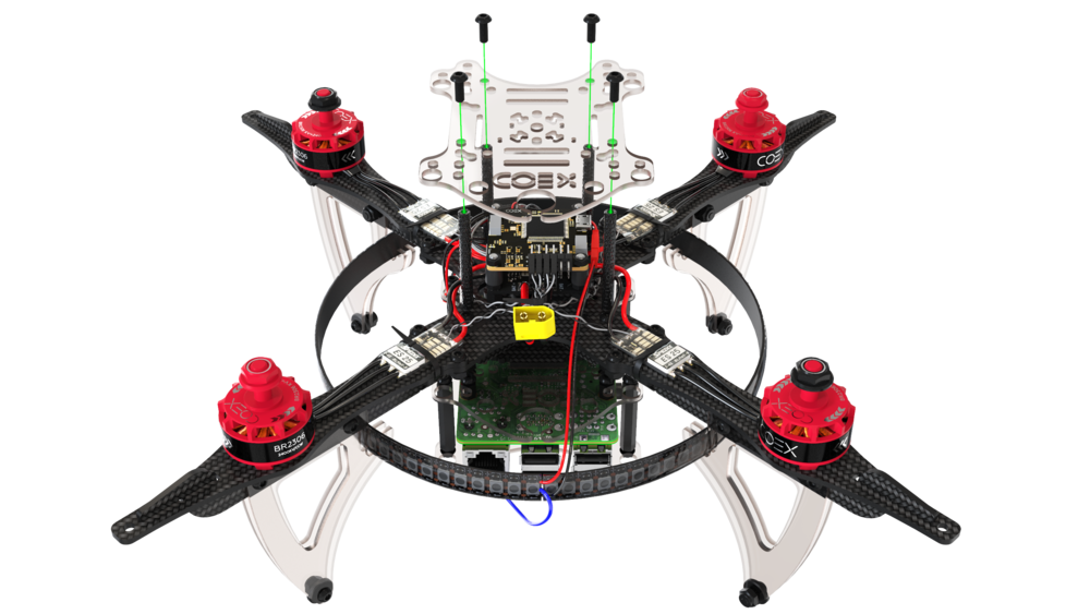
Clover 4 assembly
Dimensional drawing – clover-4.2-ws.pdf.
Fasteners size
During assembly, screws and racks of various sizes are used, using fasteners of the wrong size can damage the copter.
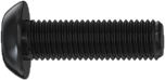 |
Screw M3x10 | 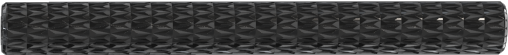 |
Aluminium rack 40mm |
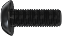 |
Screw M3x8 | 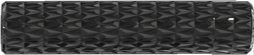 |
Aluminium rack 15mm |
| Screw M3x5 |  |
Nylon rack 40mm | |
| Screw M2x5 |  |
Nylon rack 30mm | |
| Nut M3 (self-locking) |  |
Nylon rack 20mm | |
| Nut M3 (nylon) |  |
Nylon rack 15mm | |
 |
Damper rack |  |
Nylon rack 6mm |
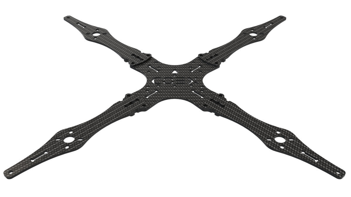
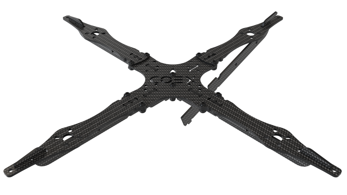
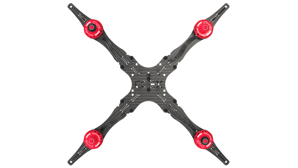
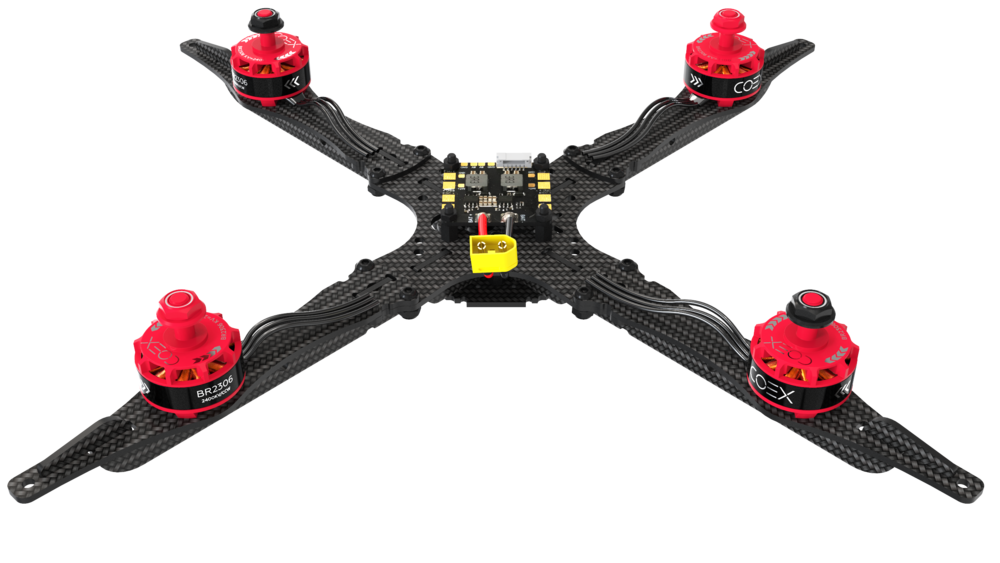
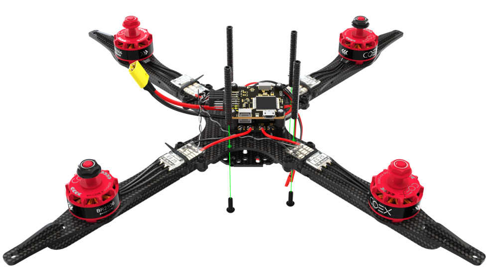
Frame Assembly
Align the 4 beams with the center deck, fix them with the M3x8 screws and self-locking nuts.
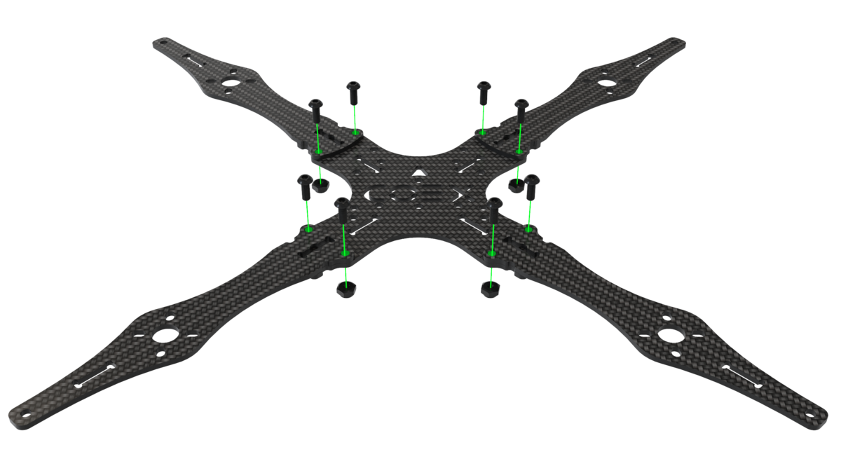
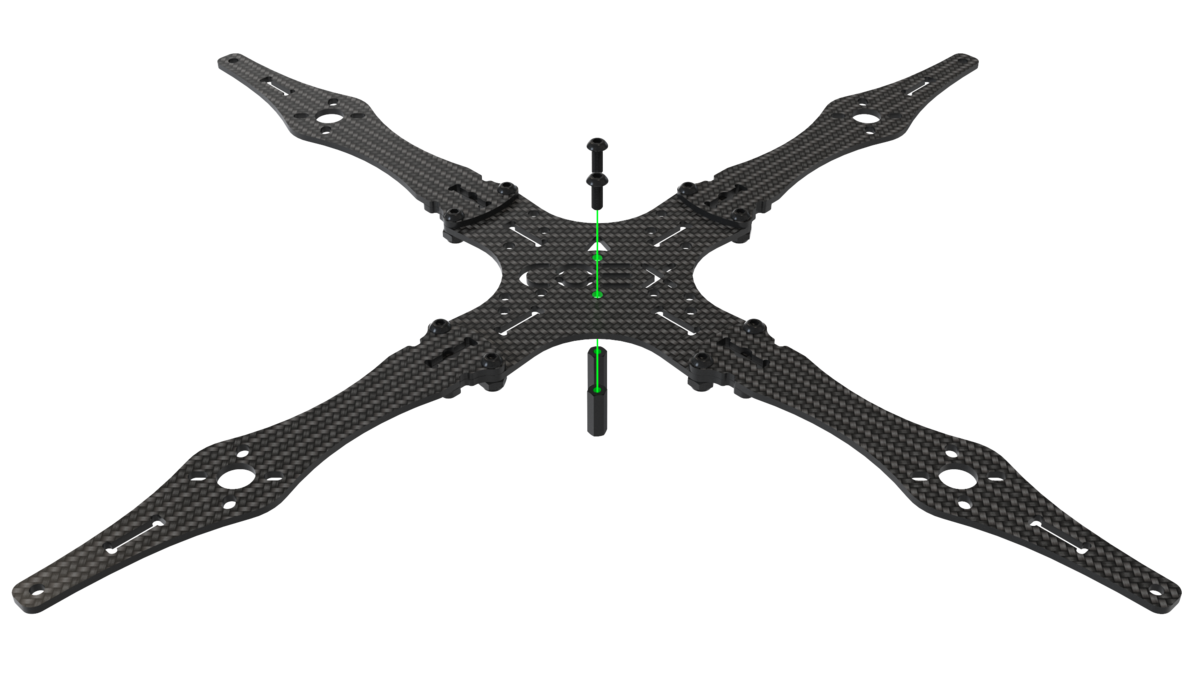
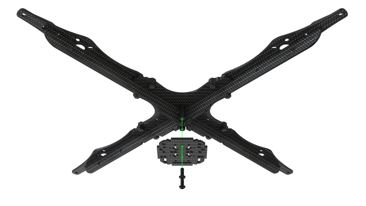
Install 2 15mm posts on the center holes in the main deck and fix them with the M3x8 screws.
Install the stiffener hook into the groove in the beam.
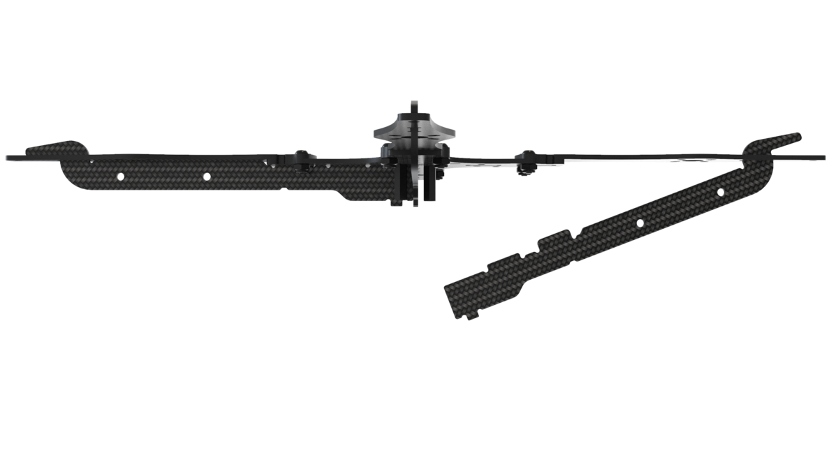
Hold the stiffeners tight to the main deck.
Tighten the stiffeners with a small carbon deck.
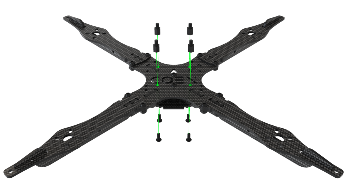
Install 4 6mm nylon posts and fix them with the M3x5 screws.
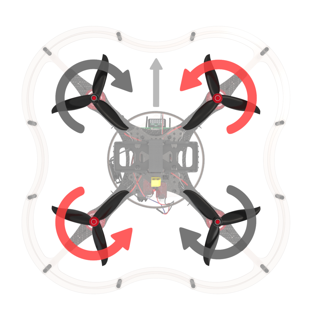
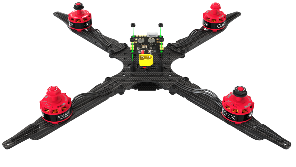
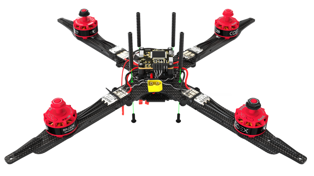
Installing of motors
When installing motors, pay attention to the rotation scheme of the motors. The rotation mark on the motors must match the rotation scheme.
Mount the motor on the corresponding holes in the beam using M3x5 screws.
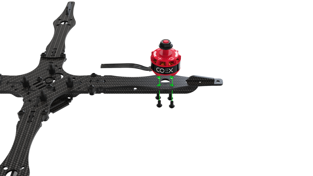
Make sure that the motors are secured with M3x5 screws, otherwise a short circuit between the windings may occur.
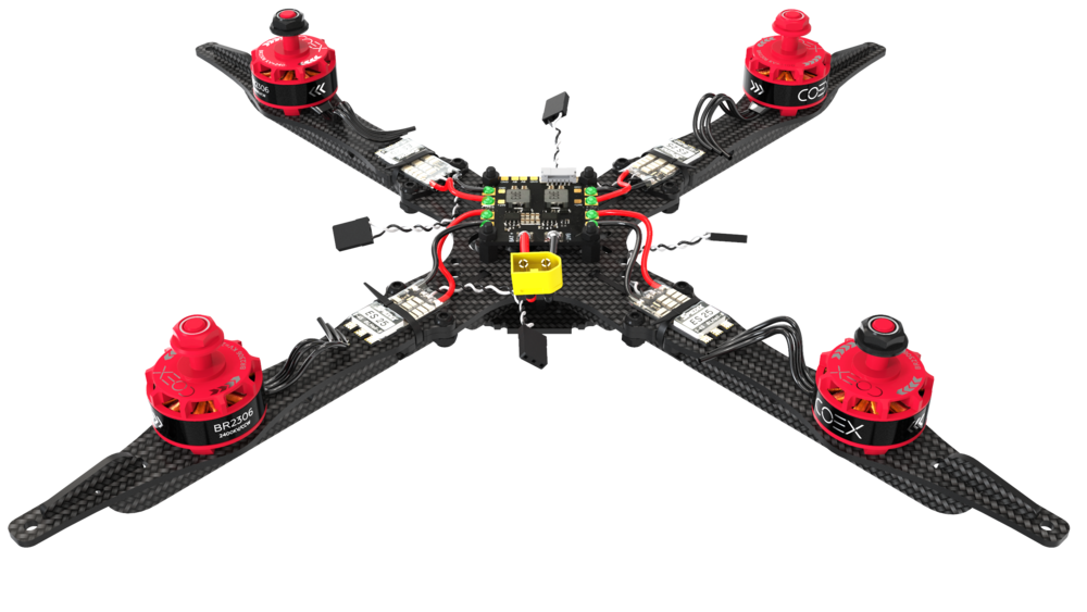
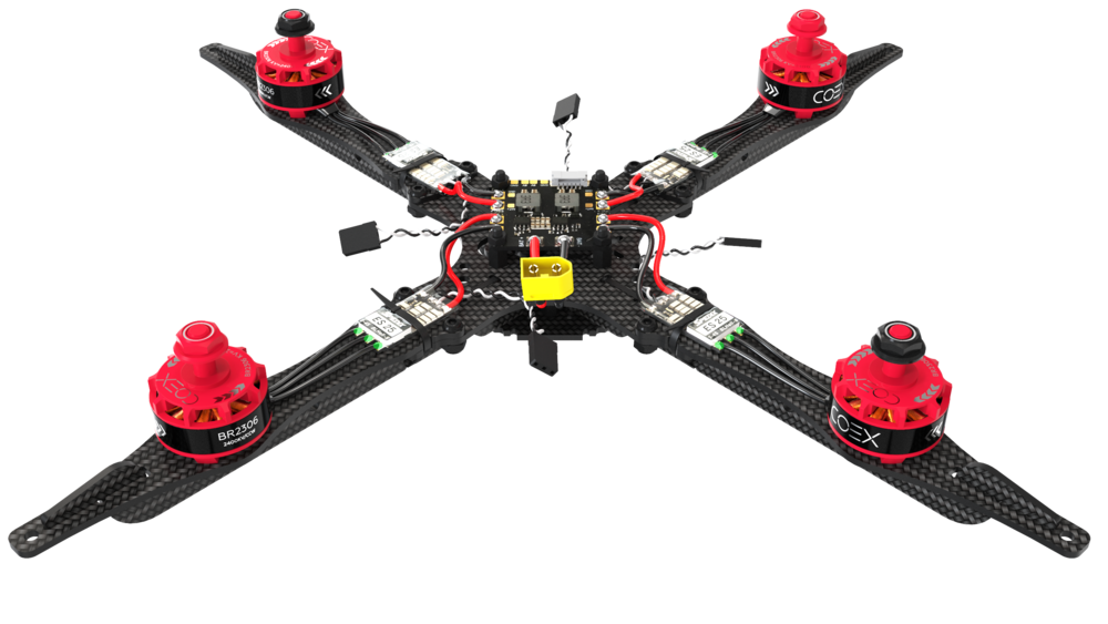
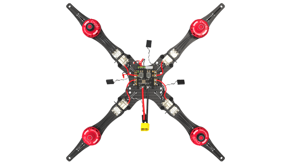
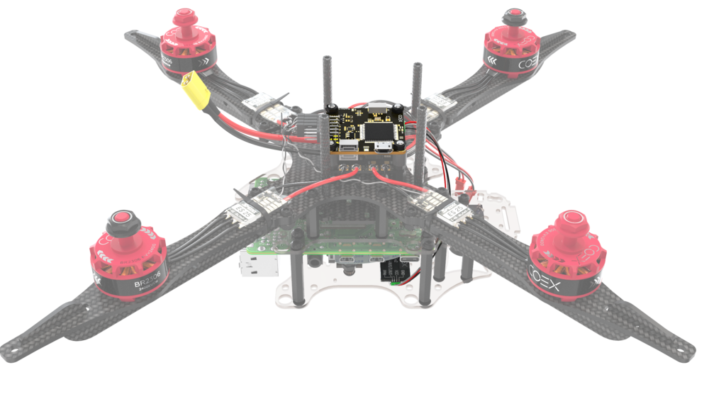
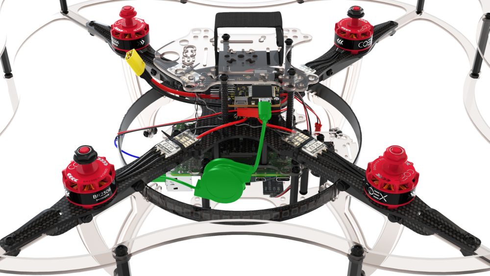
Installing ESC and PDB
Install the Power Distribution Board (PDB) on the pre-mounted stands, it must be installed with the power cable pointing towards the rear of the aircraft.
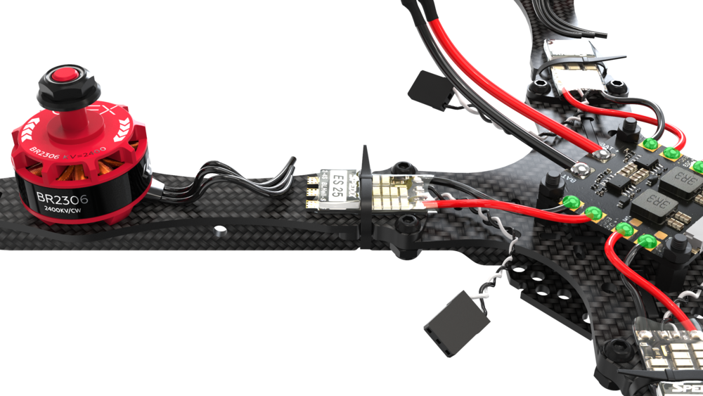
Install the speed controllers (ESC) to the appropriate positions on the beam.
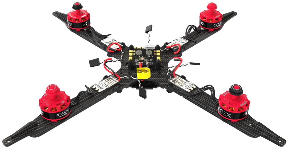
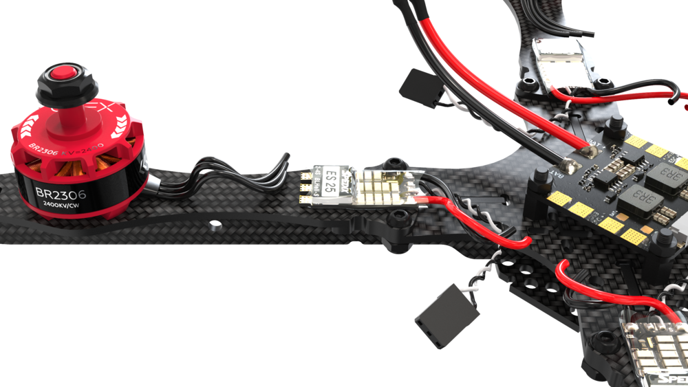
Tighten the speed controllers (ESC) with cable ties.
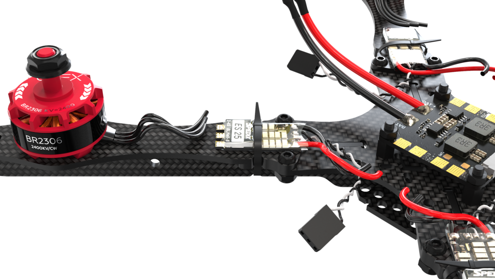
Measure out the required amount of ESC power wire, and cut off the excess.
Strip and tin the cut wires
Tin the contact pads on the power distribution board.
Solder the ESC power wires to the power distribution board.
Be careful with the pin signatures on the board. The red wire should go to the site with the signature +, and the black one to the signature -.
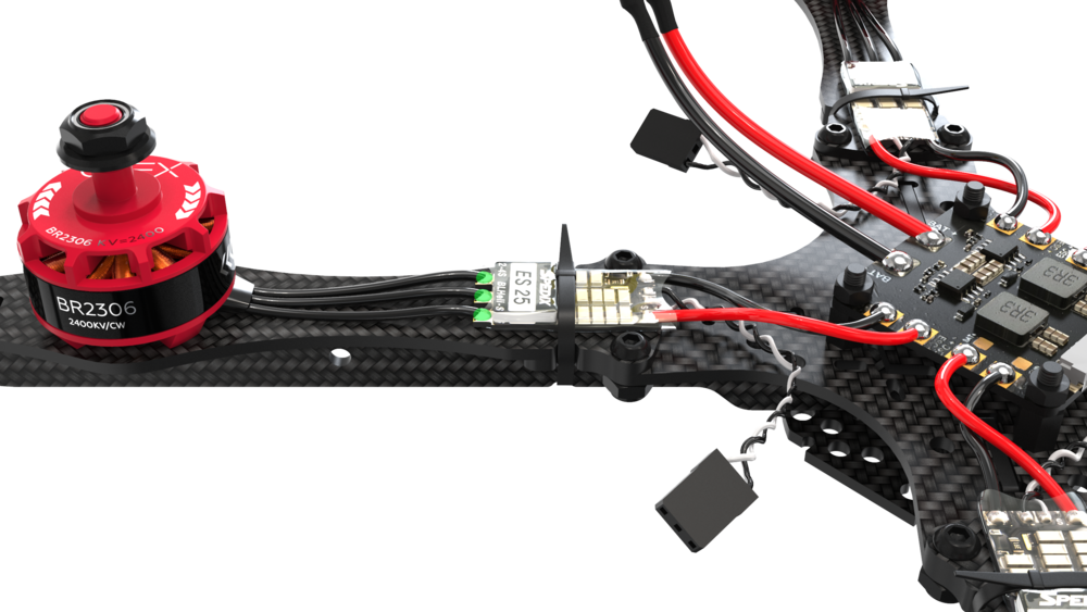
Cut off the excess phase cable coming from the motors.
Strip and tin the phase cables.
Tin the contact pads of the governors.
Solder the phase cables to the contact pads of the regulators in any order.
Solder 3 female JST connectors to 5V pads and bat+ pad
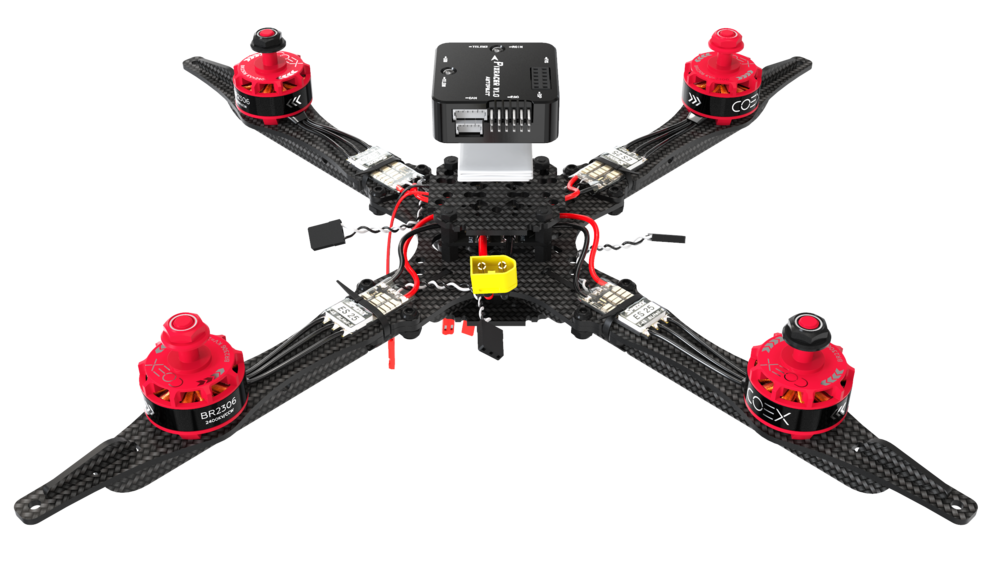
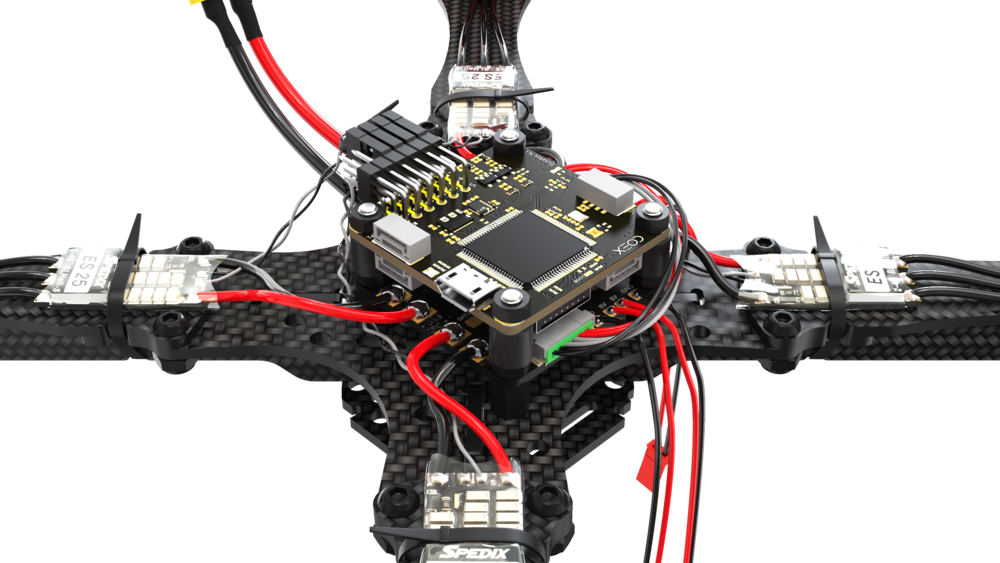
Installing the flight controller
The Clover 4 set allows you to install various flight controllers, for example COEX Pix and Pixracer.
When installing the flight controller, pay attention to the arrow located on the board, when installing it must be directed towards the nose of the aircraft.
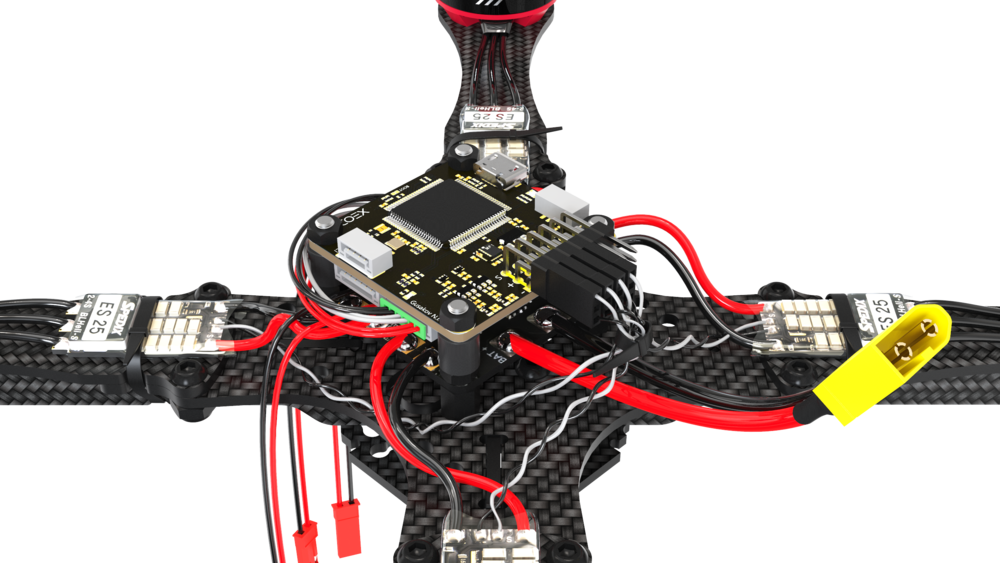
COEX Pix
Before installing the damper struts, screw in 2 layers of nylon nuts for a stronger hold or bite off excess threads with side cutters.
Secure the power distribution board with nylon nuts and mount the damper posts on top.
Install the flight controller and secure with nylon nuts.
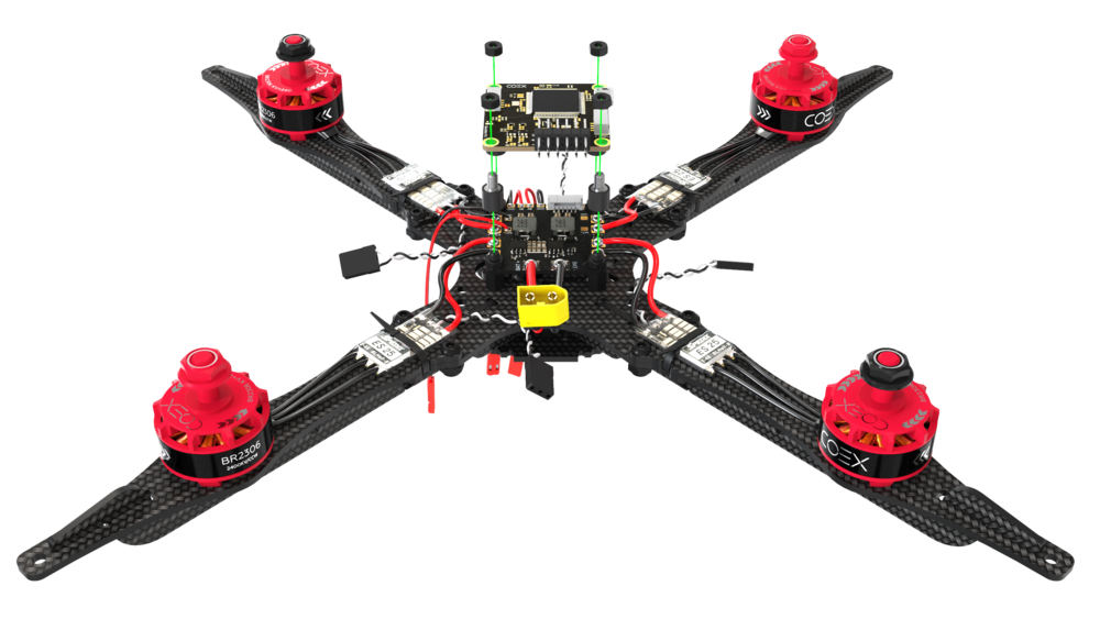
Insert the flash card for logging into the flight controller.
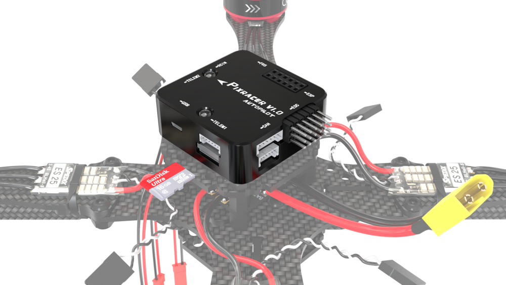
Pixracer
Secure the power distribution board with 6mm nylon struts.
Install the small mounting deck and secure with nylon nuts.
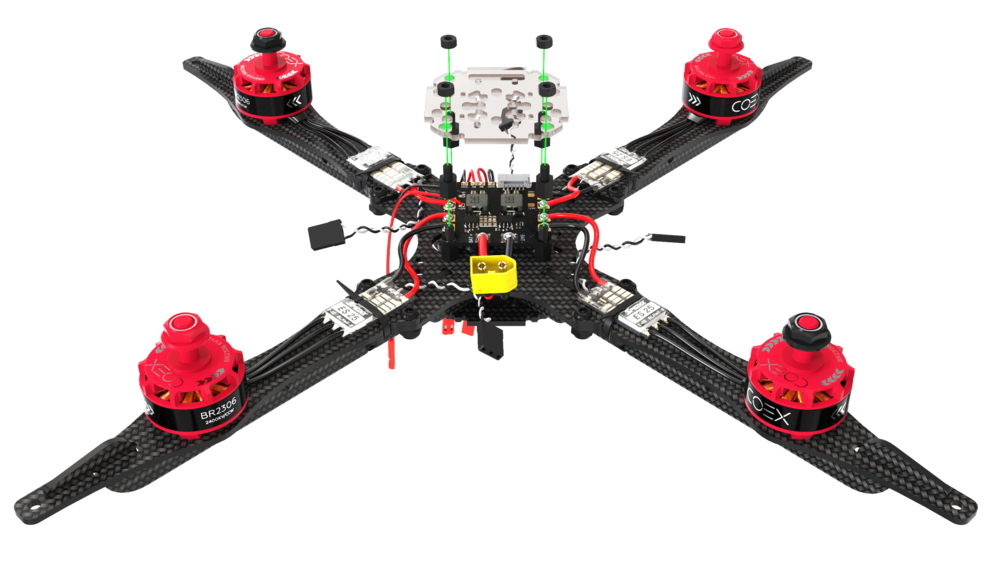
Glue 3-4 layers of double-sided tape, glue it in the center of the small deck and place the Pixracer on top.
Insert the MicroSD card into the flight controller.
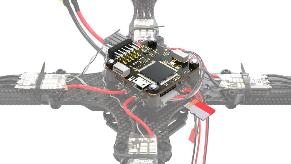
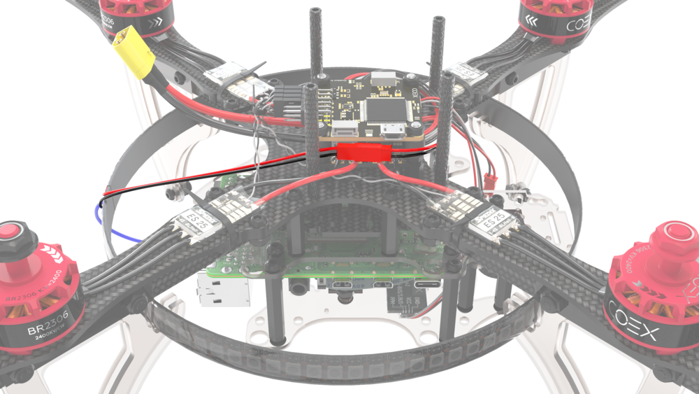
Connecting a flight controller
Connect the ESCs to the flight controller according to the scheme.
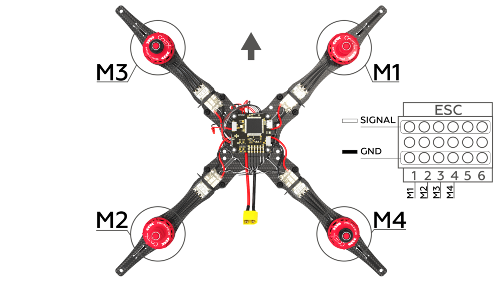
Connect the power cable to the power distribution board (PDB) and the corresponding connector on the flight controller.
Install the 40mm aluminum posts onto the M3x10 screws.
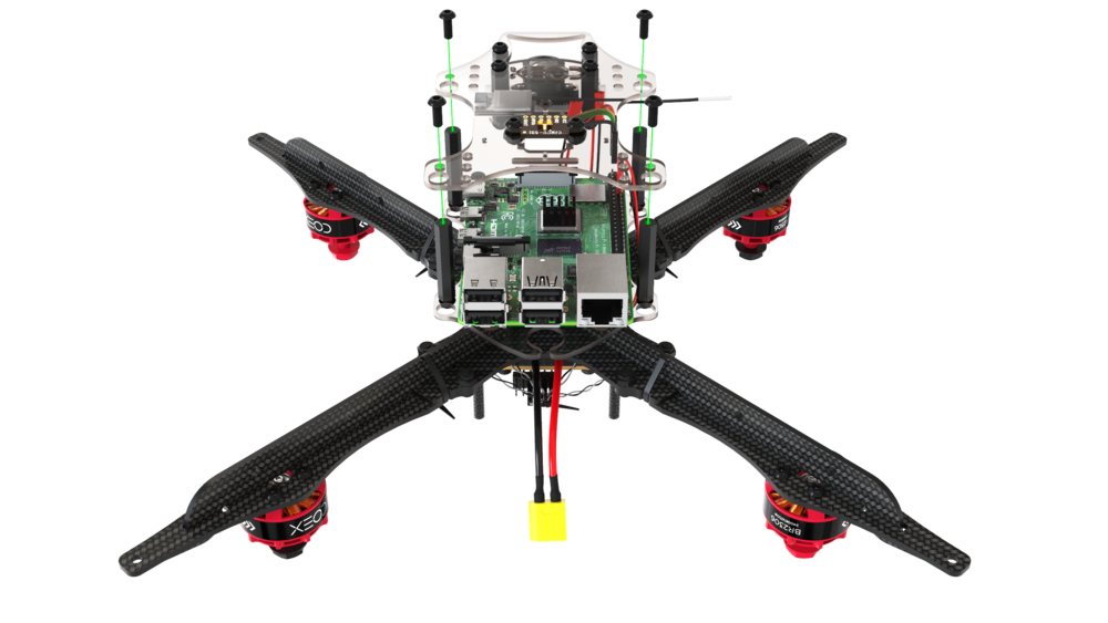
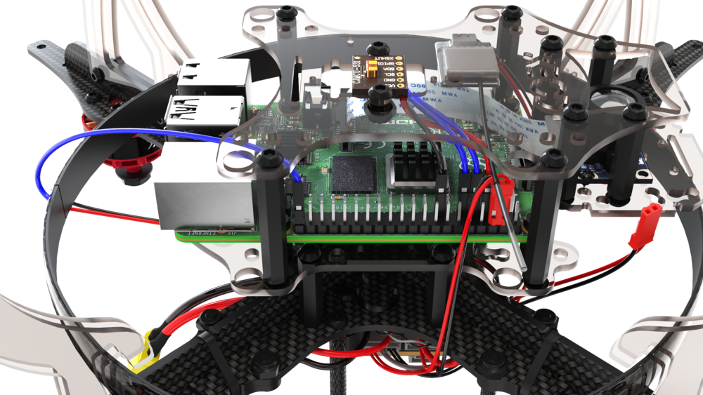
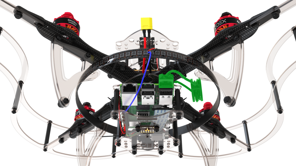
Installing Raspberry Pi
Place the 20 mm and 40 mm posts on the mounting deck, fix them with M3x8 screws.

Use an M3x10 bolt to cut M3 carving in the Raspberry Pi mounting holes.
Screw the 6mm racks into the Raspberry Pi board, secure them with nylon nuts if necessary.
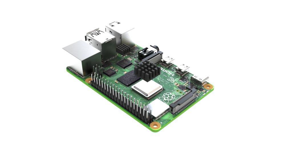
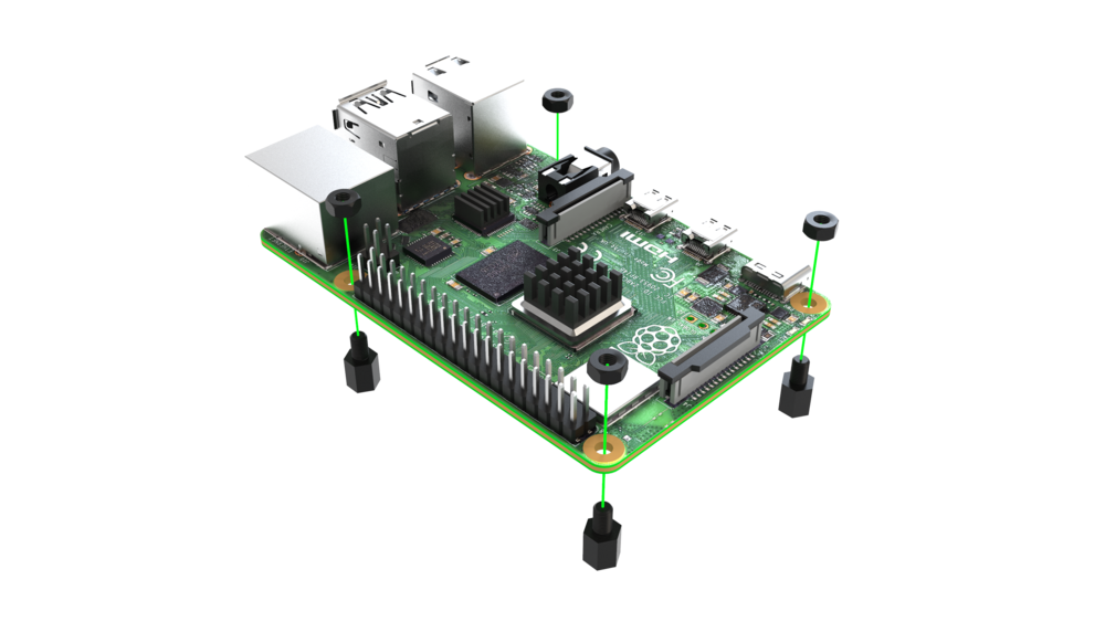
Mount the Raspberry Pi onto the mounting deck using M3x6 screws.
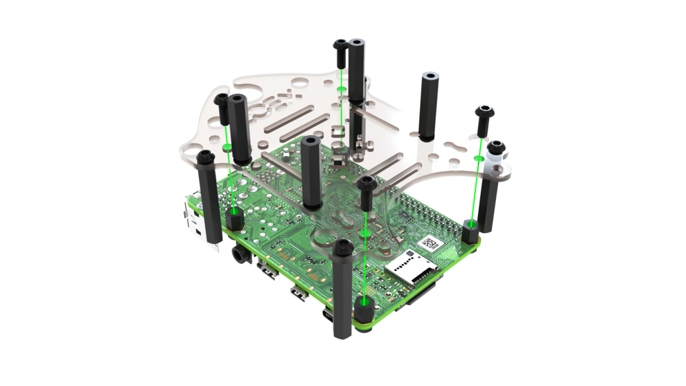
Install the assembled module into the corresponding slots on the main deck of the drone.
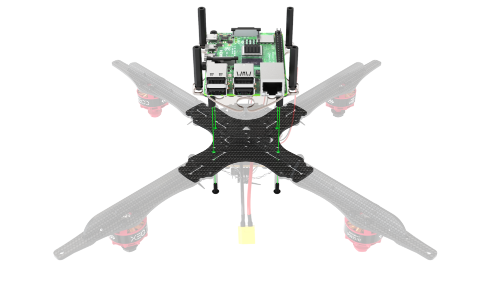
Plug the 5V JST into the corresponding power pins on the Raspberry Pi.
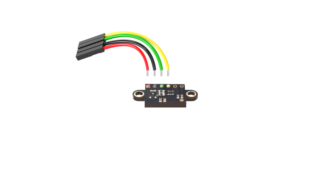
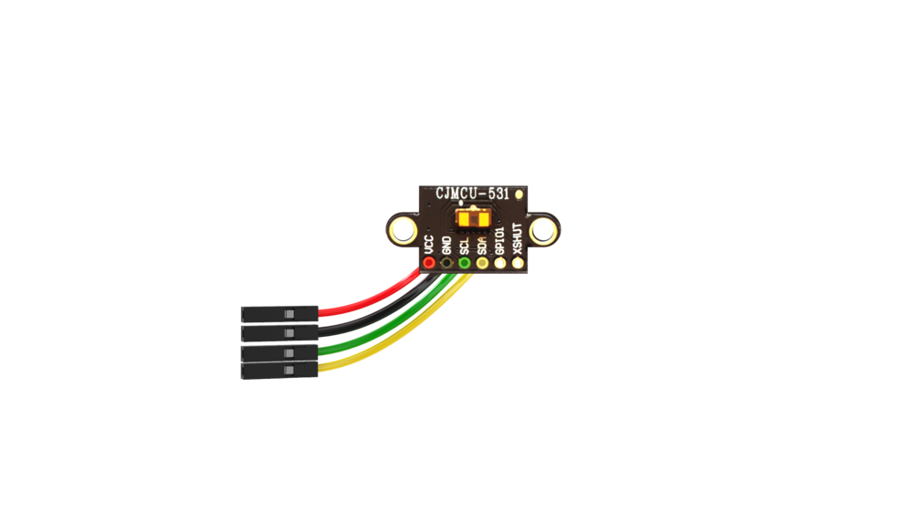
Take 4 Dupont wires, cut 5–7 cm of cable and solder to the corresponding pins of the rangefinder.
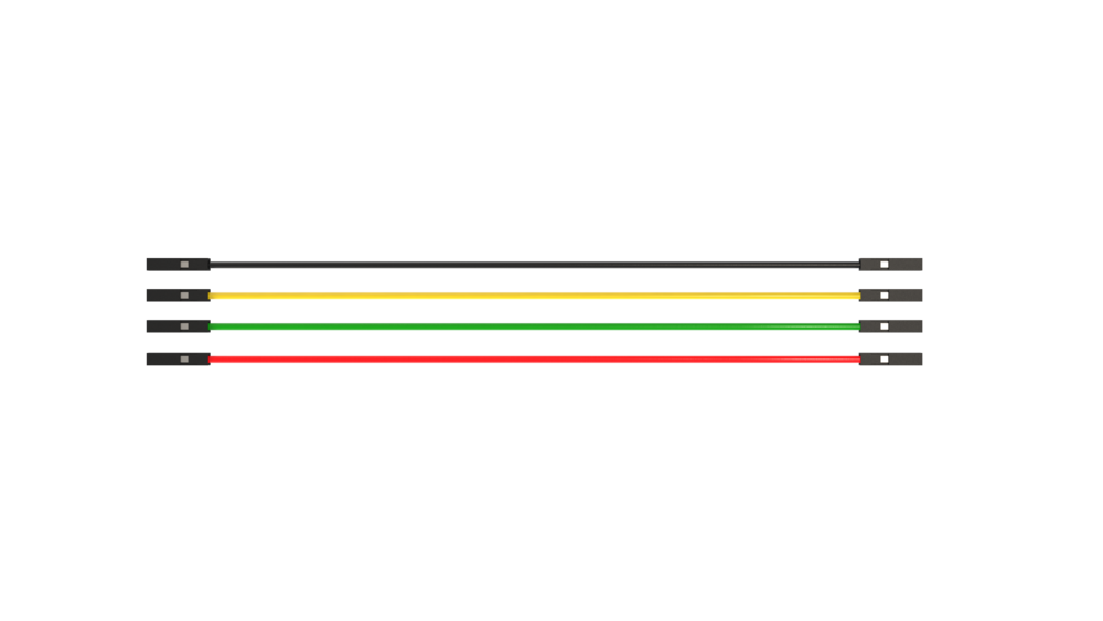
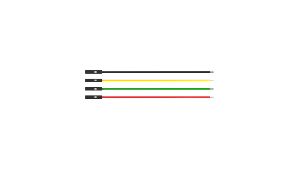
| Wire | Rangefinder pin | |------|-----------------| | Red | 5v | | Black | GND | | Yellow | SDA | | Green | SCL |
Install the rangefinder on the grip deck and glue the radio to the 3M tape.
Install the rangefinder so that the nuts do not rest directly on the board. With this installation, if there is a high probability of damaging the board elements.
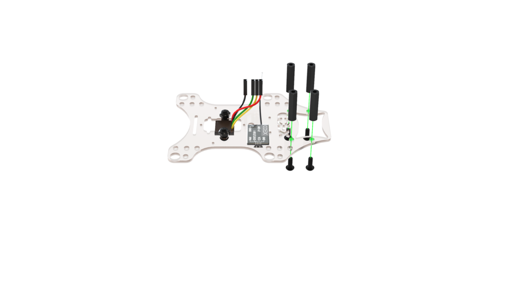
Install 4 20mm nylon posts and fix them with M3x8 bolts.
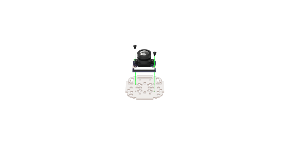
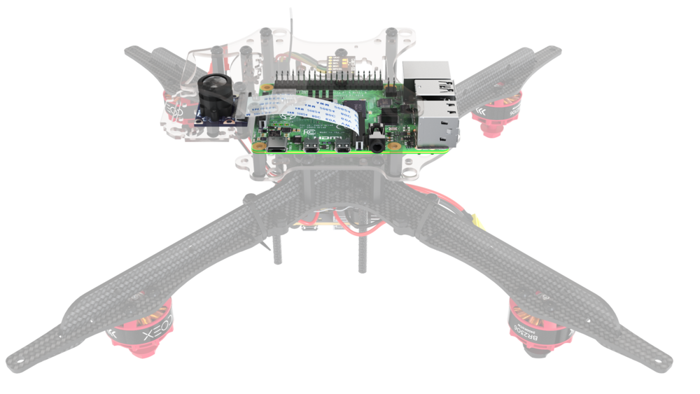
Place the camera on the small mounting deck and secure it with two short self-tapping screws.
If you attach the camera to the upper right corner and the screw head touches the element on the camera, the camera will not work.
Place the small mounting deck with the camera on the stands and secure with the M3x8 bolts.
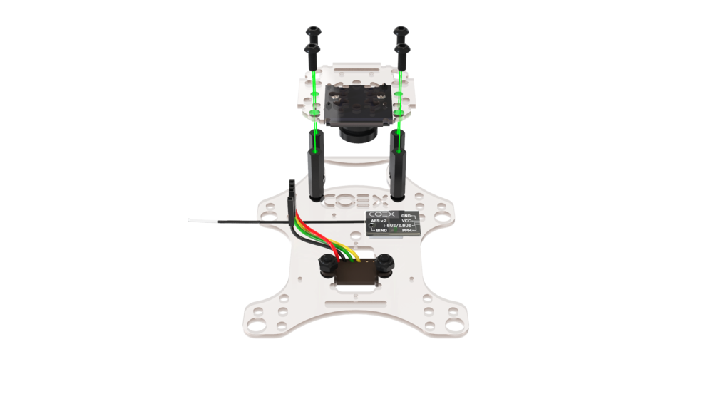
Place the assembled module over the Raspberry Pi module and fix it with M3x8 bolts.
Connect the camera and Raspberry Pi with a ribbon cable.
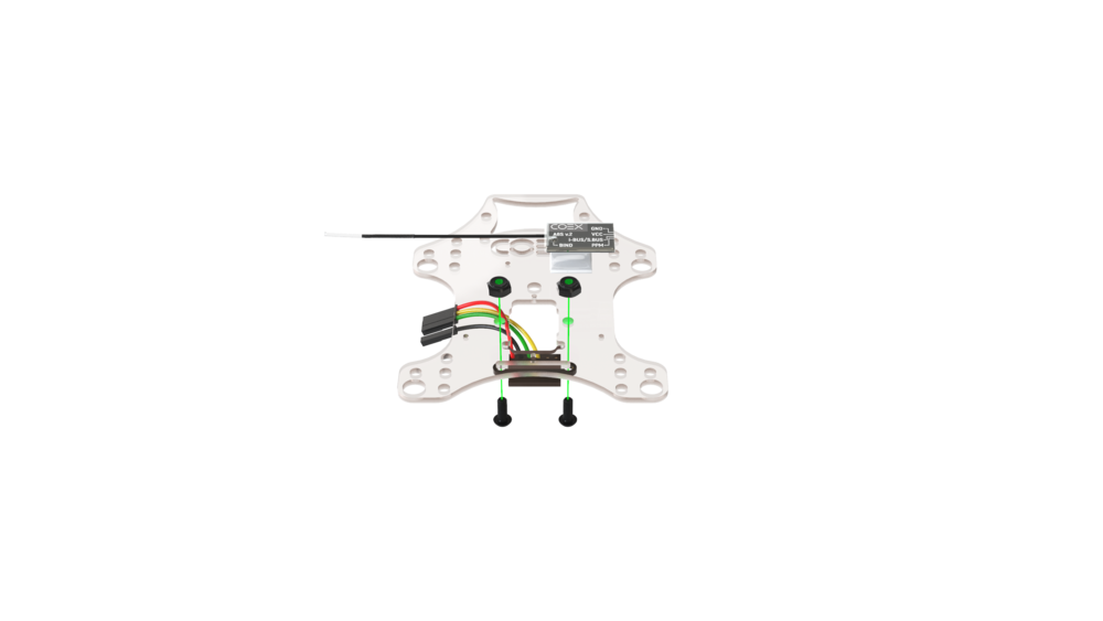
Connect the rangefinder to the Raspberry Pi into the appropriate pins.
Connect the radio and the flight controller with a 4-pin cable.
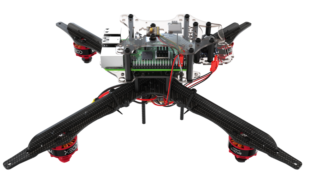
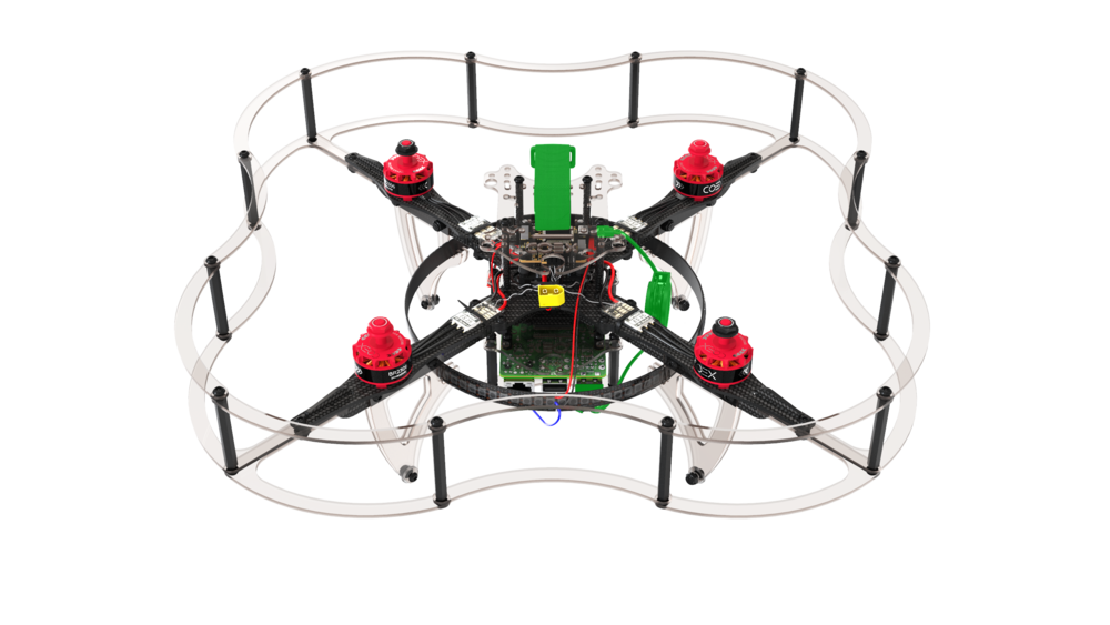
Installing LED strip and legs
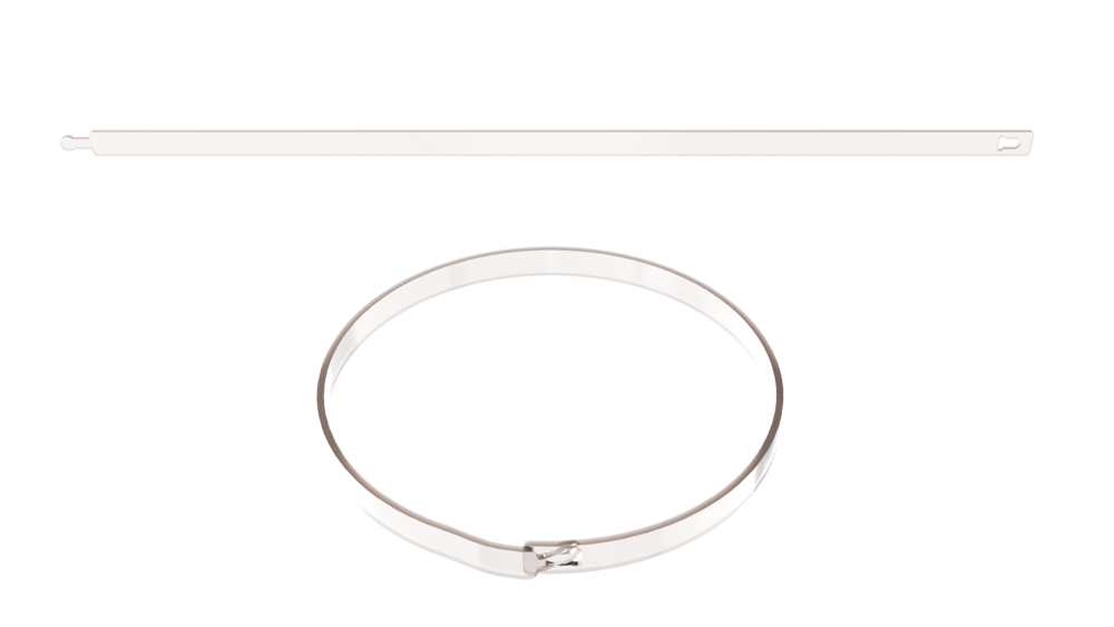
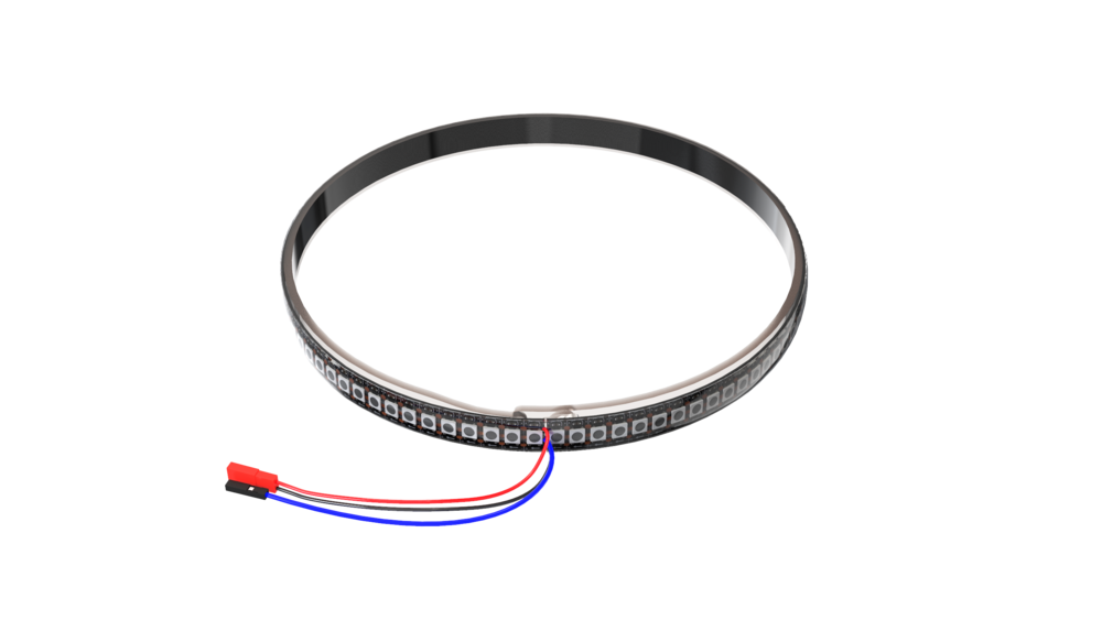
Assemble the hoop for the LED strip by locking the ends together.
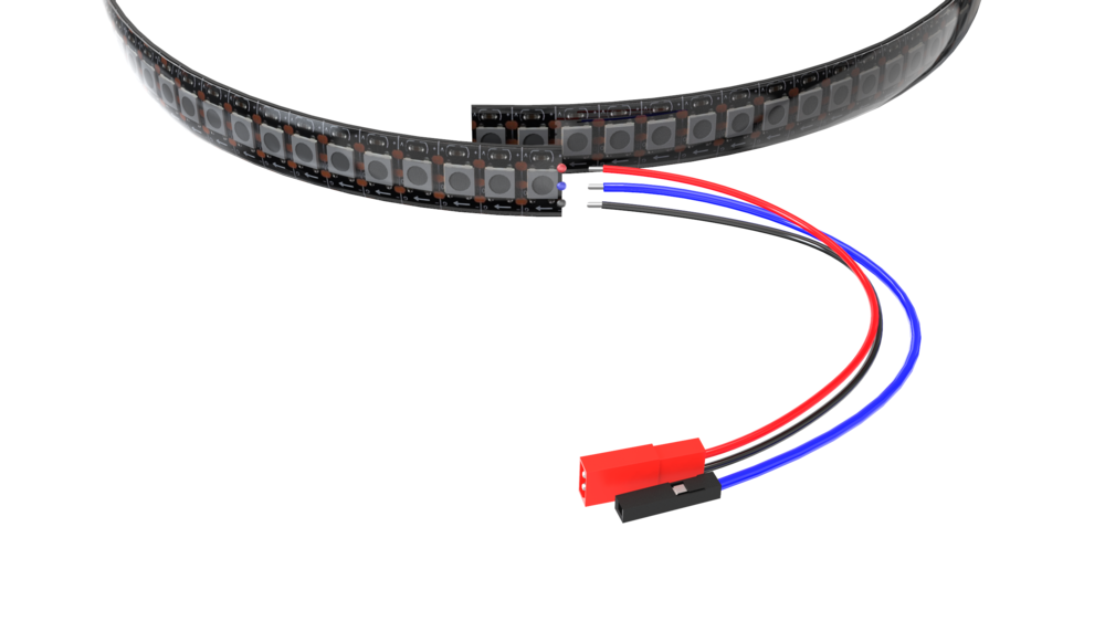
Solder the JST male to the power pad and the Dupont-female to the signal pad.
Stick the LED strip to the hoop, for greater strength, tighten it with 3-4 clamps.
Install the feet on the stiffener plate with self-locking nuts and M3x8 screws only using the outermost mounting holes. From below, between the plates of the legs, install a damper silicone ring.
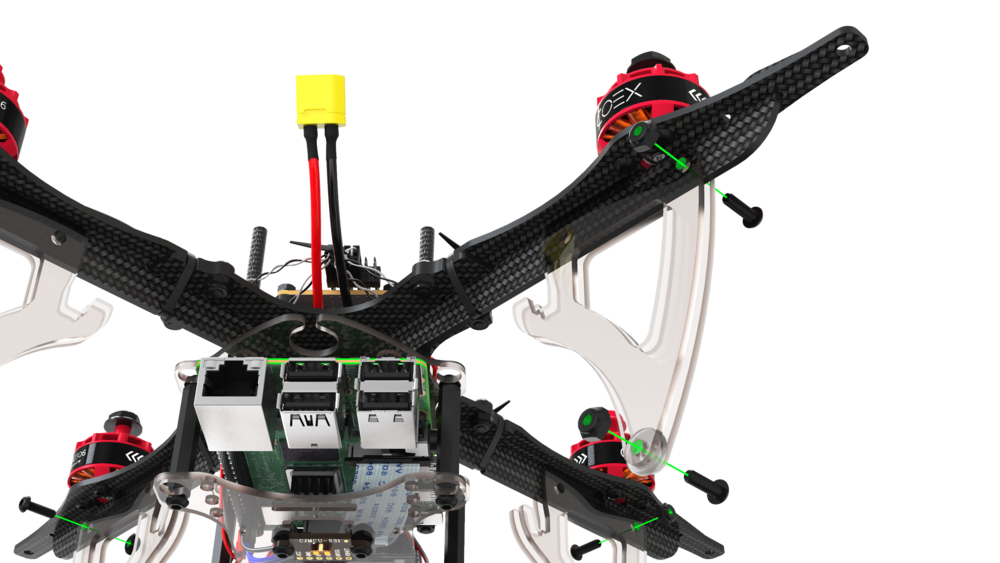
Bend the legs back and install the hoop with the LED strip in the special groove on them, so that the connection cables exit from the tail side of the copter.
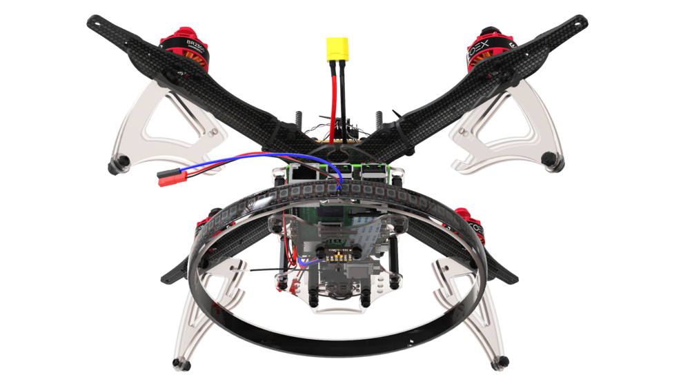
Secure the legs with self-locking nuts and M3x10 screws.
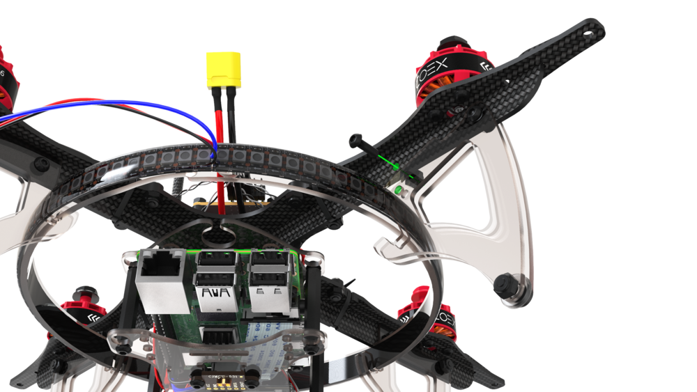
Connect the LED strip power to the JST 5V connector on the power distribution board.
Connect the signal output of the LED strip in the Raspberry Ri to pin GPIO21.
Install the mounting deck and secure it with M3x8 screws.
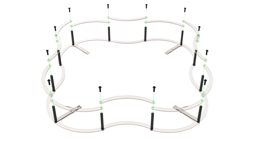
Setting protection
Assemble the lower level of protection using 40mm posts and M3x10 screws.
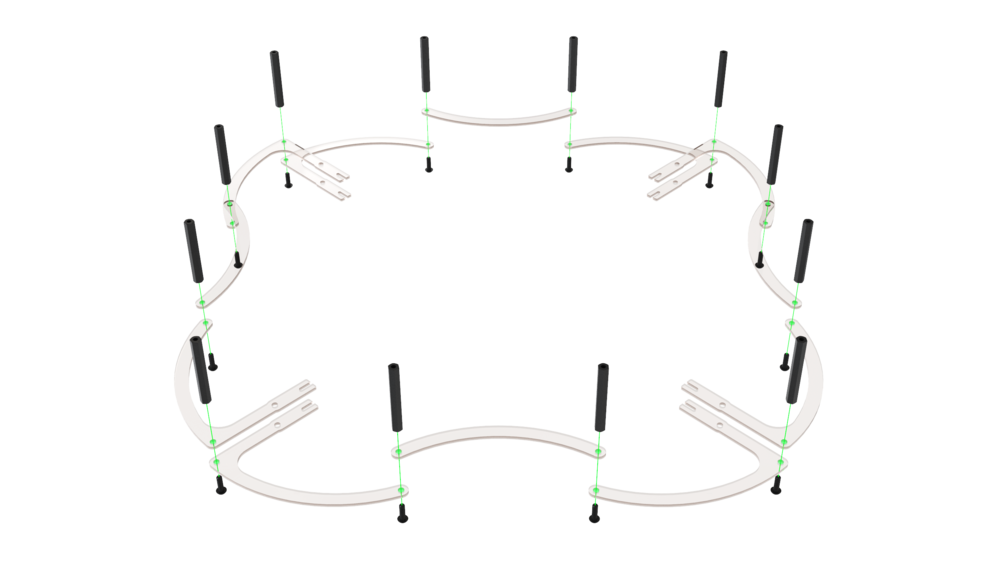
Assemble the upper layer of protection using the M3x10 screws.
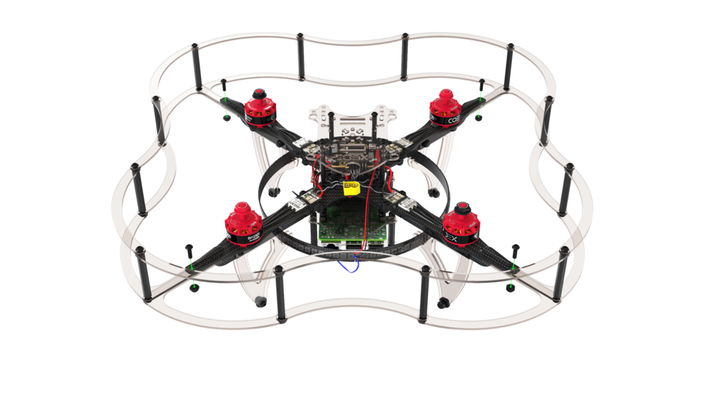
Install the protection and fix it to the beams with self-locking nuts and M3x10 screws.
Connect the flight controller to your Raspberry Pi using the USB cable.
Install the battery strap.
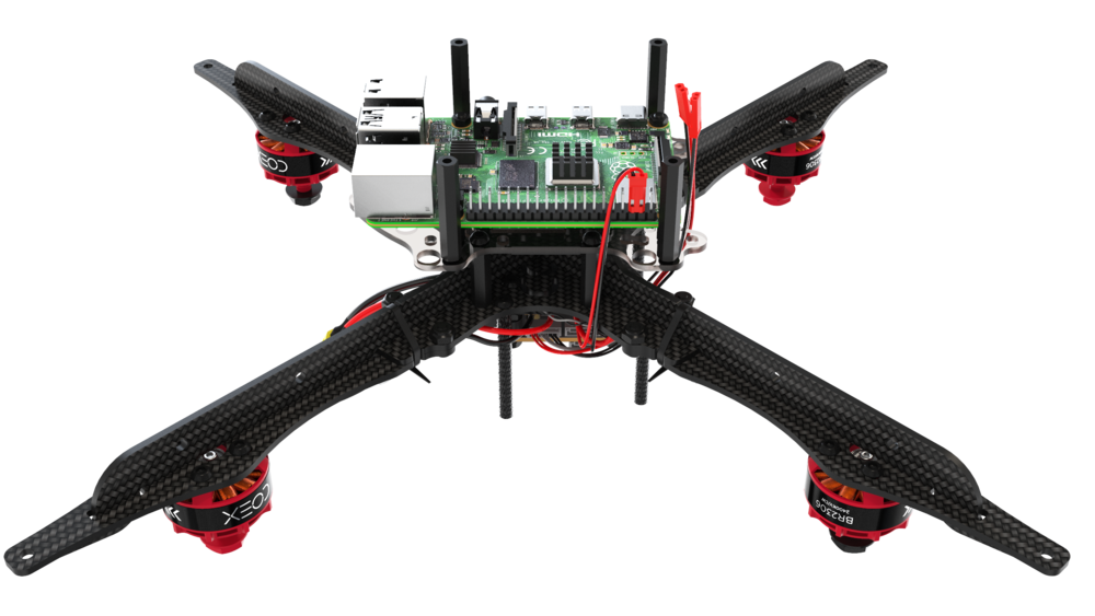
The drone is assembled, next perform the "setup" step.