Working with a LED strip on Raspberry 3
Connecting and determining the type of the strip
The following is applicable to image versions 0.14 and up. For versions 0.13 and older see an older revision of this article
Connect the +5v and GND leads of your LED to a power source and the DIN (data in) lead to GPIO18 or GPIO21 (by default).
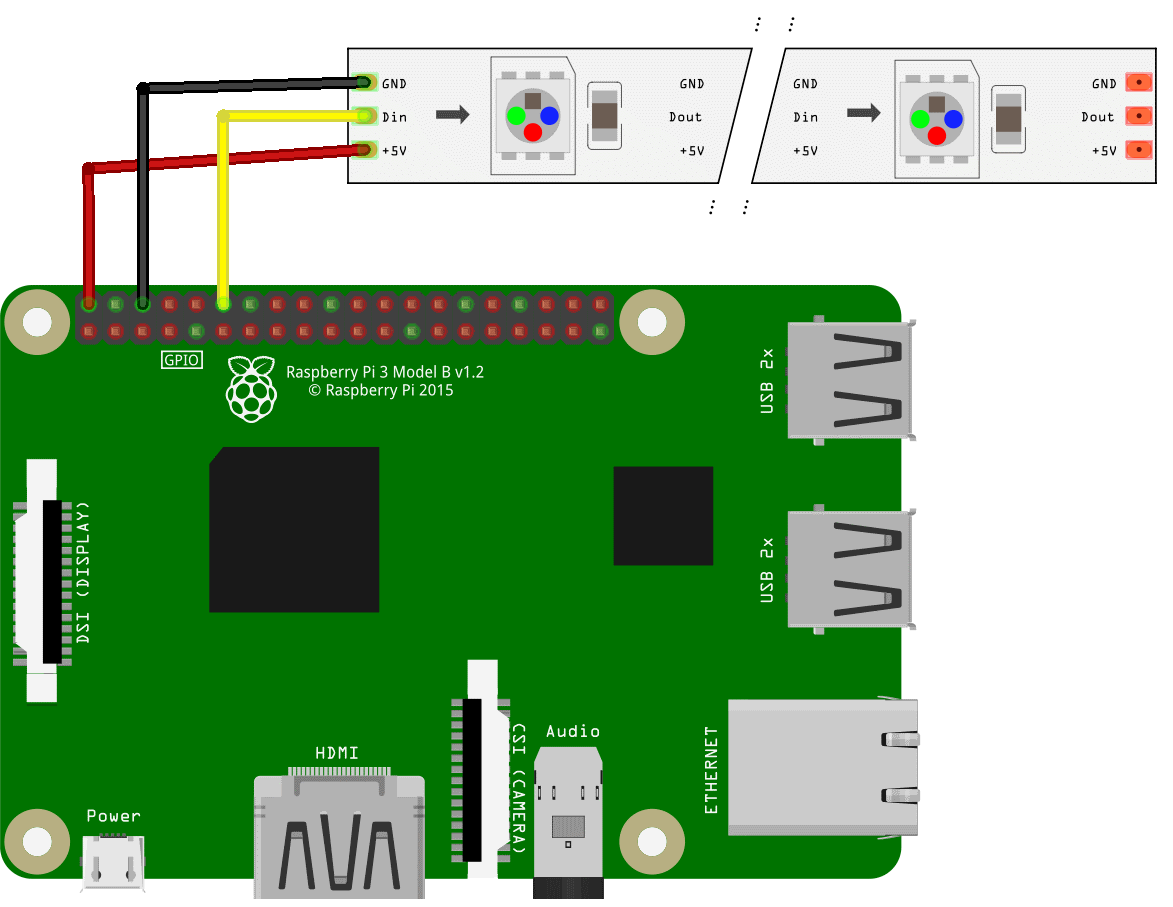
LED strip can consume a lot of power! Powering it from a Raspberry Pi may overload the computer's power circuitry. Consider using a separate BEC as a power source.
If you are using GPIO along with the LED strip, connect the strip to GPIO21. Otherwise you may experience unintended strip behavior.
ROS and Python compatibility
LED strip library requires you to run your Python scripts with sudo. In order to make it work with ROS nodes you have to add the following lines to your /etc/sudoers file on the Raspberry Pi:
Defaults        env_keep += "PYTHONPATH"
Defaults        env_keep += "PATH"
Defaults        env_keep += "ROS_ROOT"
Defaults        env_keep += "ROS_MASTER_URI"
Defaults        env_keep += "ROS_PACKAGE_PATH"
Defaults        env_keep += "ROS_LOCATIONS"
Defaults        env_keep += "ROS_HOME"
Defaults        env_keep += "ROS_LOG_DIR"
Sample program for the LED strip
The following code lights up the first 10 LEDs on the LED strip. You may use it to check whether your LED strip works correctly:
import time

from rpi_ws281x import Adafruit_NeoPixel
from rpi_ws281x import Color


LED_COUNT      = 10      # Number of LED pixels
LED_PIN        = 21      # GPIO pin for the strip
LED_FREQ_HZ    = 800000  # LED signal frequency in hertz (usually 800khz)
LED_DMA        = 10      # DMA channel to use for generating signal (try 10)
LED_BRIGHTNESS = 255     # Set to 0 for darkest and 255 for brightest
LED_INVERT     = False   # True to invert the signal (when using NPN transistor level shift)
LED_CHANNEL    = 0       # Set to '1' for GPIOs 13, 19, 41, 45 or 53

strip = Adafruit_NeoPixel(LED_COUNT, LED_PIN, LED_FREQ_HZ, LED_DMA, LED_INVERT)

strip.begin()


def colorWipe(strip, color, wait_ms=50):
    """Wipe color across strip a pixel at a time."""
    for i in range(strip.numPixels()):
        strip.setPixelColor(i, color)
        strip.show()
        time.sleep(wait_ms/1000.0)


print('Color wipe animations.')
colorWipe(strip, Color(255, 0, 0), wait_ms=100)  # Red wipe
colorWipe(strip, Color(0, 255, 0), wait_ms=100)  # Blue wipe
colorWipe(strip, Color(0, 0, 255), wait_ms=100)  # Green wipe
colorWipe(strip, Color(0, 0, 0), wait_ms=100)    # Turn LEDs off
You may also want to use additional test scripts from the LED library repository.
Save the script and run it as root:
sudo python led_test.py
Basic LED library functions
You'll need to import Adafruit_NeoPixel class and Color function into your program to interact with the LED strip. Additionally, you'll want the time module to add delays to your animations:
from rpi_ws281x import Adafruit_NeoPixel
from rpi_ws281x import Color
import time
Instantiate the Adafruit_NeoPixel object and call its begin() method to start working with the strip:
# Strip object instantiation (parameter description is provided in a code snippet above)
strip = Adafruit_NeoPixel(LED_COUNT, LED_PIN, LED_FREQ_HZ, LED_DMA, LED_INVERT)
strip.begin()
Main strip control methods:
numPixels()returns the number of pixels in the strip. Convenient for whole strip operations.setPixelColor(pos, color)sets the pixel color atpostocolor. Color should be a 24-bit value, where the first 8 bits are for the red channel, the next 8 bits are for the green channel, and the last 8 bits are for the blue channel. You may use theColor(red, green, blue)convenience function to convert colors to this format. Each color value should be an integer in the [0..255] range, where 0 means zero brightness and 255 means full brightness.SetPixelColorRGB(pos, red, green, blue)sets the pixel atposto the color value with componentsred,greenandblue. Each component value should be an integer in the [0..255] range, where 0 means zero brightness and 255 means full brightness.show()updates the strip state. Any changes to the strip state are only pushed to the actual strip after calling this method.
Does it have to be this way?
The LED strip type used in the Clover kits use the following protocol: a data source (a Raspberry Pi, for example) sends a bit stream, 24 bits per LED. Each LED reads the first 24 bits from the stream and sets its color accordingly while passing the rest of the stream to the next LED. Zeroes and ones are encoded by different pulse lengths.
This LED strip is supported by the rpi_ws281x library. The library uses the DMA (direct memory access) module of the Raspberry CPU and can utilize one of the three periphery channels: PWM, PCM or SPI. This allows the library to drive the strip consistently in a multitasking environment.
Each channel has its caveats. Using the PWM prevents you from using the builtin Raspberry audio subsystem; using the PCM channel will prevent you from adding I2S (digital audio) devices, although the analog audio will work. SPI requires you to change your GPU and buffer size and prevents you from using any SPI devices.
Some DMA channels are reserved for system use. DMA channel 5 is used for SD card reads and writes, and setting LED_DMA to 5 will corrupt your filesystem. DMA channel 10 is considered to be safe.
You have the following options for the LED strip:
- If you don't need onboard audio, you may use the PWM channel and connect the LED strip to one of the following GPIO pins: 12, 18, 40 or 52 for PWM0 and 13, 19, 41, 45 or 53 for PWM1.
If you don't care about SPI devices, you may use the SPI channel for the LED with GPIO pins 10 or 38. You'll have to perform the following adjustments:
- increase the SPI device buffer by adding
spidev.bufsiz=32768option to/boot/cmdline.txt; - set the GPU frequency to 250 MHz by adding
core_freq=250to/boot/cmdline.txt; - reboot your Raspberry Pi:
sudo reboot.
- increase the SPI device buffer by adding
- If you care about audio and SPI devices, you may want to use the PCM channel (GPIO 21 or 31). You don't have to reconfigure your Raspberry.
The default option is 3, because it allows the builtin audio system to work and does not require any modifications to the boot sequence.